ماژول
مقایسه
تصویر
دیتا شیت
نام
توضیح کوتاه
سازنده
اندازه
قیمت
MOQ
سبد خرید
-
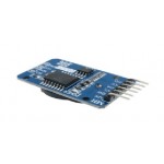


(DS3231 AT24C32 IIC Module Precision Clock Module DS3231SN for Arduino Memory module (with battary
Description
The DS3231 is a low-cost, extremely accurate...Description
The DS3231 is a low-cost, extremely accurate I²C real-time clock (RTC) with an integrated temperature-compensated crystal oscillator (TCXO) and crystal. The device incorporates a battery input, and maintains accurate timekeeping when main power to the device is interrupted. The integration of the crystal resonator enhances the long-term accuracy of the device as well as reduces the piece-part count in a manufacturing line. The DS3231 is available in commercial and industrial temperature ranges, and is offered in a 16-pin, 300-mil SO package.
The RTC maintains seconds, minutes, hours, day, date, month, and year information. The date at the end of the month is automatically adjusted for months with fewer than 31 days, including corrections for leap year. The clock operates in either the 24-hour or 12-hour format with an active-low AM/PM indicator. Two programmable time-of-day alarms and a programmable square-wave output are provided. Address and data are transferred serially through an I²C bidirectional bus.
A precision temperature-compensated voltage reference and comparator circuit monitors the status of VCC to detect power failures, to provide a reset output, and to automatically switch to the backup supply when necessary. Additionally, the active-low RST pin is monitored as a pushbutton input for generating a µP reset.
Features
Accuracy ±2ppm from 0°C to +40°C
Accuracy ±3.5ppm from -40°C to +85°C
Battery Backup Input for Continuous Timekeeping
Operating Temperature Ranges
Commercial: 0°C to +70°C
Industrial: -40°C to +85°C
Low-Power Consumption
Real-Time Clock Counts Seconds, Minutes, Hours, Day, Date, Month, and Year with Leap Year Compensation Valid Up to 2100
Two Time-of-Day Alarms
Programmable Square-Wave Output
Fast (400kHz) I²C Interface
3.3V Operation
Digital Temp Sensor Output: ±3°C Accuracy
Register for Aging Trim
Active-Low RST Output/Pushbutton Reset Debounce Input
Chinaندارد۵۰۰٬۵۰۰ ریال۱ -

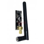
2.4g Nrf24l01 PA LNA SMA Antenna Wireless Transceiver Communication Module
description:
This wireless transceiver module is an easy...description:
This wireless transceiver module is an easy and suitable module if you want to setup your wireless communication system with low cost!! It can achieve a good balance between wireless transition performance and cost! You can easily add it with your own MCU/ARM/PIC/AVR/STM32 system! What\'s more, this NRF24L01+ module is designed with Power amplifier and SMA antenna. This allowed you to use the wireless communication up to 1000 meters! (No barrier)
Frequence: 2.4GHz~2.5GHz
Operating voltage: 3 ~ 3.6V Max
Current: 115mA
Multi-frequency: 125 frequency
Support up to six channels of data reception
Communication distance: up to 1000 meters (No barrier)
Chinaندارد۹۱۱٬۶۰۰ ریال۱ -

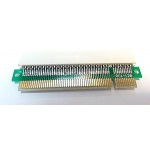
ADAP-PCI to PCIE-120
مبدل PCI به PCIE روی اسلات مادر برد 120پایه
Chinaندارد۴۱۸٬۲۰۰ ریال از: ۴۰۶٬۷۰۰ ریال۱ -

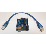
ARDUINO DEVELOPMENT BOARD
arduino development bord Treedix 2pcs ATmega328P CH340 Development Boar
...arduino development bord Treedix 2pcs ATmega328P CH340 Development Board Compatible with Arduino UNO R3 Board Kit for Starter
The board is a microcontroller board based on the CH340. It has 14 digital input/output pins (of which 6 can be used as PWM outputs), 6 inputs, a 16 MHz ceramic resonator, a USB connection, a power jack, an ICSP header, and a reset button. This is compatible board with an Atmega328p and a CH340G serial converter, 100% Compatible with Arduino UNO R3. This board has the following new features: 1.0 pinout: added SDA and SCL pins that are near to the AREF pin and two other new pins placed near to the RESET pin, the IOREF that allow the shields to adapt to the voltage provided from the board. In future, shields will be compatible with both the board that uses the AVR, which operates with 5V and with the Due that operates with 3.3V. The second one is a not connected pin, that is reserved for future purposes. Stronger RESET circuit. Friendly: the board is easy to use for Arduino starter, It contains everything needed to support the microcontroller; simply connect it to a computer with a USB cable or power it with a AC-to-DC adapter or battery to get started. We strive to put our hundred percent to meet your requirements and try our best to achieve your satisfaction!
Chinaندارد۴٬۹۷۷٬۵۰۰ ریال از: ۴٬۹۵۰٬۰۰۰ ریال۱ -

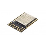
ESP-12E
ESP8266 ESP-12F Serial WIFI Model ESP-12E Upgrade Remote Wireless WIFI Module ESP12F ESP12
Chinaندارد۷۷۰٬۰۰۰ ریال از: ۷۵۶٬۳۰۰ ریال۱ -

ESP-WROOM-32 (4MB)
WiFi Modules (802.11) SMD Module, ESP32-D0WD, 32Mbits 4Mb SPI Flash, UART mode, U.fl Ant Connector
Chinaندارد۱٬۶۵۰٬۰۰۰ ریال۱ -
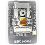

esp32-cam
Features: - Ultra-small 802.11b/g/n Wi-Fi + BT/BLE SoC module
...Features: - Ultra-small 802.11b/g/n Wi-Fi + BT/BLE SoC module - Low-power dual-core 32-bit CPU for application processors - Up to 240MHz, up to 600 DMIPS - Built-in 520 KB SRAM, external 4M PSRAM - Supports interfaces such as UART/SPI/I2C/PWM/ADC/DAC - Support OV2640 and OV7670 cameras with built-in flash - Support for WiFI upload -Support TF card - Support multiple sleep modes - Embedded Lwip and FreeRTOS - Support STA/AP/STA+AP working mode - Support Smart Config/AirKiss One-click distribution network - Support for serial local upgrade and remote firmware upgrade (FOTA) Description: CES NEWS' Geekcreit ESP32-CAM WiFi + Bluetooth Camera Module Development Board ESP32 With Camera Module OV2640 2MP - Board & Shield Motherboard & Development Board. The ESP32-CAM has a very competitive small-size camera module that can operate independently as a minimum system, measuring the only 27*40.5*4.5mm, with deep sleep current and a minimum of 6mA. ESP-32CAM can be widely used in various IoT applications. It is suitable for home smart devices, industrial wireless control, wireless monitoring, QR wireless identification, wireless positioning system signals and other IoT applications. It is an solution for IoT applications. ESP-32CAM is packaged in and can be directly plugged into the backplane for quick production. It provides customers with a highly reliable connection method and is convenient for use in various IoT hardware terminals. Note: This product contains the OV2640 Camera Module. If you need to use the OV7670 camera, please purchase it separately. Package Included: 1 x ESP32-CAM Module 1 x Camera Module OV2640 2MP Product Specifications: ESP32-CAM Picture Output Format Rate: Test environment: camera model: OV2640 XCLK: 20
Chinaندارد۲٬۵۰۲٬۵۰۰ ریال۱ -
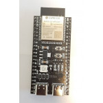

ESP32-S3-WROOM-1
About this item 32 bit MCU, 2.4 GHz WiFi + Bluetooth LE SoC Suppor
...About this item 32 bit MCU, 2.4 GHz WiFi + Bluetooth LE SoC Supporting IEEE 802.11 b/g/n and Bluetooth 5 Based on ESP32-S3-WROOM-1 8MB Flash + 2 MB PSRAM About ESP32-S3 hardware resources ESP32-S3 is a low-power MCU-based SoC that supports 2.4 GHz Wi-Fi and Bluetooth Low Energy (Bluetooth LE). ESP32-S3 has a complete Wi-Fi subsystem and a Bluetooth LE subsystem, State-of-the-art power and RF performance. S3 provides a rich set of peripheral interfaces, and supports ultra-low-powerapplications. Different security features allow the device to meet stringent security requirements. Instructions for using the USB cable The on-board USB port of the YD-ESP32-S3 core board is the Type-C interface.It can communicate with the computer and provide power. The cable can be used: USB Type A to Type-C cable or CC cable Note the distinction between the commonly used USB A port to Type-C cable that can only be charged, which cannot be used for communication between YD-ESP32-S3 and the host.
Chinaندارد۲٬۵۱۹٬۰۰۰ ریال از: ۲٬۴۷۵٬۰۰۰ ریال۱ -

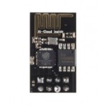
ESP8266 ESP-01 Serial WIFI Wireless Transceiver Module Send Receive LWIP AP+STA
Overview:
This is WiFi serial transceiver module, based...Overview:
This is WiFi serial transceiver module, based on ESP8266 SoC.
The SOC has Integrated TCP/IP protocol stack
We have a set of documents in Chinese. We are preparing tutorials and demo software to showcase utility of this module.
ESP8266 is a highly integrated chip designed for the needs of a new connected world. It offers a complete and self-contained Wi-Fi networking solution, allowing it to either host the application or to offload all Wi-Fi networking functions from another application processor.
ESP8266 has powerful on-board processing and storage capabilities that allow it to be integrated with the sensors and other application specific devices through its GPIOs with minimal development up-front and minimal loading during runtime. Its high degree of on-chip integration allows for minimal external circuitry, and the entire solution, including front-end module, is designed to occupy minimal PCB area.
Corresponding Interface:
SDIO 2.0, SPI, UART
32-pin QFN package
Integrated RF switch, balun, 24dBm PA, DCXO, and PMU
Integrated RISC processor, on-chip memory and external memory interfaces
Integrated MAC/baseband processors
Quality of Service management
I2S interface for high fidelity audio applications
On-chip low-dropout linear regulators for all internal supplies
Proprietary spurious-free clock generation architecture
Integrated WEP, TKIP, AES, and WAPI engines
Specification:
802.11 b/g/n
Wi-Fi Direct (P2P), soft-AP
Integrated TCP/IP protocol stack
Integrated TR switch, balun, LNA, power amplifier and matching network
Integrated PLLs, regulators, DCXO and power management units
+19.5dBm output power in 802.11b mode
Power down leakage current of <10uA
Integrated low power 32-bit CPU could be used as application processor
SDIO 1.1/2.0, SPI, UART
STBC, 1×1 MIMO, 2×1 MIMO
A-MPDU & A-MSDU aggregation & 0.4ms guard interval
Wake up and transmit packets in < 2ms
Standby power consumption of < 1.0mW (DTIM3)
Chinaندارد۷۵۰٬۸۰۰ ریال۱ -
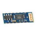

ESP8266 ESP-03 Serial Wifi Wireless Transceiver Module Send Receiver LWIP AP+STA
Description
1. Support 802.11 B/G/N
2. Communicat...Description
1. Support 802.11 B/G/N
2. Communication range up to 100 yards depending on environment.
3. Standard 3.3VDC operation with 5V compatible I/O.
4. Standard 3 wire (TXD/RXD/GND) serial communication (idle high) at 115200/8/N/1.
5. Standard 0.1" (2.54mm) half through hole.
6. Upgradeable firmware.
7. Three mode of operations: Client/Access Point/Both Client and Access Point.
8. Support all major security schemes: OPEN/WEP/WPA_PSK/WPA2_PSK/WPA_WPA2_PSK.
9. Support both TCP and UDP communication.
10. Working as TCP/UPD server supports up to five (5) connections.
11. Working as station can connect up to 5 TCP/UPD servers. The ESP-04 can connect to all standard non-SSL websites in the world.
12. Simple AT commands for all operations.
13. Connection based data reception or transparent data reception.
14. Programmable client connection inactivity timeout.
15. Automatic domain name address resolution for public domain name but not the local name within the local area network (router).
Chinaندارد۱٬۲۳۳٬۳۰۰ ریال۱ -

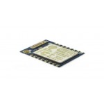
ESP8266 ESP-07 Serial WIFI Wireless Transceiver Wireless Module LWIP AP+STA
Description:
1X(The ESP8266 is a chip highly designed fo...Description:
1X(The ESP8266 is a chip highly designed for the needs of a new connected world.
It offers a complete and self-contained Wi-Fi network solution, allowing you to either host the application or download all Wi-Fi network functions from another application processor.
Its high degree of integration on the chip allows minimal external circuitry, and the complete solution, including the input section module, is designed to occupy a minimum area of PCB.
Dimensions: 4 x 3 x 0.3 cm
Color: Blue; 100% New and high quality. This product is your best choice. Do not hesitate. It is time to replace your old, worn, damaged product.
Materials: CCL
Warnings:
This module requires a voltage supply of 3.3 for VCC, and 3.3V of logic.
Can not accept 5V.
Connecting the RX or TX over 5V Arduino will destroy this module.
You must use a logic level converter, or a 3.3V for Arduino
The supply of 3.3V on the Arduino Uno has an inadequate current capacity to power this module.
It must provide a separate power supply and higher than 3.3V (approximately 300mA or better)
Package includes:
1 x Wireless WiFi Remote Transducer Module ESP8266 Serial Esp-07 LWIP AP + STA
Only the above package content, other products are not included.
Note: Light shooting and different displays may cause the color of the item in the picture a little different from the real thing. The measurement allowed error is +/- 1-3cm.)
Chinaندارد۱٬۱۶۱٬۸۰۰ ریال۱ -

Esp8266 Remote Serial Port WiFi Transceiver Wireless Module Esp-05 AP Sta
Features:
SDIO 2.0, SPI, UART , 32-pin QFN package , Int...Features:
SDIO 2.0, SPI, UART , 32-pin QFN package , Integrated RF switch, balun, 24dBm PA, DCXO, and PMU , Integrated RISC processor, on-chip memory and external memory interfaces , Integrated MAC/baseband processors , Quality of Service management
I2S interface for high fidelity audio applications , On-chip low-dropout linear regulators for all internal supplies , Proprietary spurious-free clock generation architecture , Integrated WEP, TKIP, AES, and WAPI engines Solutions
Specifications: 802.11 b/g/n , Wi-Fi Direct (P2P), soft-AP , Integrated TCP/IP protocol stack , Integrated TR switch, balun, LNA, power amplifier and matching network , Integrated PLLs, regulators, DCXO and power management units , +19.5dBm output power in 802.11b mode
Power down leakage current of <10uA , Integrated low power 32-bit CPU could be used as application processor , SDIO 1.1/2.0, SPI, UART , STBC, 1?1 MIMO, 2?1 MIMO , A-MPDU & A-MSDU aggregation & 0.4ms guard interval , Wake up and transmit packets in < 2ms , Standby power consumption of < 1.0mW (DTIM3)Description:
ESP8266 is a highly integrated chip designed for the needs of a new connected world. It offers a complete and self-contained Wi-Fi networking solution, allowing it to either host the application or to offload all Wi-Fi networking functions from another application processor. , ESP8266 has powerful on-board processing and storage capabilities that allow it to be integrated with the sensors and other application specific devices through its GPIOs with minimal development up-front and minimal loading during runtime. Its high degree of on-chip integration allows for minimal external circuitry, and the entire solution, including front-end module, is designed to occupy minimal PCB area.
Chinaندارد۱٬۳۴۰٬۶۰۰ ریال۱ -

ESP8266 Remote Serial Port WIFI Transceiver Wireless Module ESP-12E AP+STA
Overview:
ESP8266 is a highly integrated chip designed f...Overview:
ESP8266 is a highly integrated chip designed for the needs of a new connected world. It offers a complete and self-contained Wi-Fi networking solution, allowing it to either host the application or to offload all Wi-Fi networking functions from another application processor.Description:
Breakthrough design, there are new breakthroughs, based on ESP-12E.
The new four-layer board design.
The new revision antenna RF performance optimization, communication distance is increased by 30% -50% compared to ESP-12E!
Semi-hole chip technology, the whole IO leads, with metal shielding shell
Passed FCC & CE & RoHS certification
Built-board PCB antenna
4M bytes SPI Flash for programming.
ESP8266 has powerful on-board processing and storage capabilities that allow it to be integrated with the sensors and other application specific devices through its GPIOs with minimal development up-front and minimal loading during runtime. Its high degree of on-chip integration allows for minimal external circuitry, and the entire solution, including front-end module, is designed to occupy minimal PCB area.Features:
Standards Certification: FCC / CE / TELEC
Wireless standards: 802.11 b / g / n
Frequency range: 2.4GHz-2.5GHz (2400M-2483.5M)
Data interface: UART / HSPI / I2C / I2S / Ir Remote Contorl GPIO / PWM
Operating voltage: 3.0 ~ 3.6V (recommendation 3.3V)
Working Current: Average: 80mA
Operating temperature: -40 ° ~ 125 °
Storage temperature: Nomal temperatu
Chinaندارد۱٬۳۵۴٬۳۰۰ ریال از: ۱٬۳۳۳٬۸۰۰ ریال۱ -

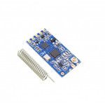
HC-12
Description The HC-12 is a 100mW multi-channel wireless transceiver you
...Description The HC-12 is a 100mW multi-channel wireless transceiver you can use in your projects to transmit and receive serial information. The HC-12 is a half-duplex wireless serial communication module with 100 channels in the 433.4-473.0 MHz range that is capable of transmitting up to 1 km. This project will begin by using the HC-12 to create a wireless link between two computers and end with a second article that creates a simple wireless GPS tracker.
Chinaندارد۲٬۵۴۳٬۸۰۰ ریال از: ۲٬۵۱۶٬۳۰۰ ریال۱ -
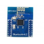

Low Power Consumption BLE4.0 Bluetooth 2.4 GHz Wireless Module NRF51822
Overview:
Core51822 is a wireless module based on nRF518...Overview:
Core51822 is a wireless module based on nRF51822 - the Multiprotocol Bluetooth® 4.0 low energy/2.4 GHz RF SoC designed for ULP (ultra low power) wirelesss applications.
Core51822 Specifications
Onboard chip: nRF51822
Communication distance (open outdoor@1M data rate): 30m
Frequency range: 2.4GHz
Operating voltage: 2.0V ~ 3.6V
Operating temperature: -40℃ ~ 85℃
Dimension (PCB): 24.5mm x 32.26mm
Expansion pinheader: all the I/Os except P0.26 and P0.27
Pinheader pitch: 2.00mm
Spacing between pinheaders on the left side and the right side: 18.00mm
Antenna: onboard antenna
NRF51822 Features:
2.4 GHz multiprotocol RF transceiver
ARM® Cortex™-M0 32 bit processor
128 bit AES HW encryption
128kB flash & 16Kb RAM
Programmable Peripheral Interconnect (PPI)
Digital interfaces: SPI, I2C, UART
10 bit ADC
Programmable output power: -20 to +4 dBm
Independent application development and protocol stack
Fully compatible with NRF24L series
Pinout compatible with NRF51xxx series
Global separate power management
Operating voltage: 1.8 V ~ 3.6 V
Applications:
Wearable devices
Bluetooth intelligent application
Mobile phone accessories
RFID labels
Smart home appliances
Industry control
Data acquisition system
Revision History
2015.06, Core51822 upgrades the onboard chip to Rev3, features RAM 16K,
supports higher version SDK, and all the demo codes are still compatible with the Rev2 ones.
Package Include:
1 x Low Power Consumption BLE4.0 Bluetooth 2.4 GHz Wireless Module NRF51822
Chinaندارد۱٬۶۲۶٬۶۰۰ ریال۱ -
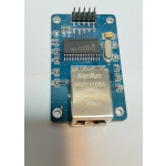

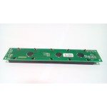
MiNi ENC28J60 Ethernet LAN Network Module
Brand new and high quality. Chip board ENC28J60-I/SO. The boa
...Brand new and high quality. Chip board ENC28J60-I/SO. The board 25MHZ crystal. The network interface board HR911105A. 3.3 V supply pin. Debug reminder: 1, the IP address of the computer to a network segment and module such as IP module 192.168.1.2, IP computer set: 192.168.1.3; 192.168.1 is the 3 section; 2, the network cable connected to the mouth of the computer network module and mouth; (that is, the cable network 1 3,2 , and then do not understand that there are pictures Baidu); 3, the module and the MCU connection should pay attention to the connection of each line is reliable (the surface is not even connected to the good); 4, and the MCU port IO to confirm that is right; 5, the program recompile, download, confirm whether to download! STM32 and 51 IO size:48 x 18mm Material:plastic colour:blue Package Contents: 1 x Ethernet Shield Only the above package content, other products are not included. Note: Light and different displays may cause the color of the item in the picture a little different from the real thing. The measurement allowed error is +/- 1-3cm.
Chinaندارد۲٬۳۷۸٬۸۰۰ ریال از: ۲٬۳۵۱٬۳۰۰ ریال۱ -
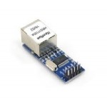

MiNi ENC28J60 Ethernet LAN Network Module SPI AVR PICSTM32 for Arduino
Description
Chip board ENC28J60/SS.
The board 25MHZ...Description
Chip board ENC28J60/SS.
The board 25MHZ crystal.
The network interface board HR911105A.
3.3V power supply pin.
Size: 48.8 (mm) x 18.5 (mm).
Chinaندارد۱٬۳۵۸٬۵۰۰ ریال۱ -

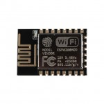
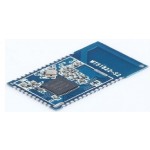
Module V2 ESP8266 ESP 12E
Size: 18*18*2.8 (±0.2)mm- SPI Flash: 1MB-The type of interface: UART/GPIO/ADC/PWM-The quantity of I
... Size: 18*18*2.8 (±0.2)mm- SPI Flash: 1MB-The type of interface: UART/GPIO/ADC/PWM-The quantity of IO put: 11 Series rate: 300-4608000 bps, the default is 115200bps-RF range: 2412-2484MHz-RF range: 2412-2484MHz The type of antenna: onboard PCB wire Transmission power: 802.11b: 16±2 dB (@11Mbps) 802.11g: 14±2 dB (@54Mbps) 802.11n: 13±2 dB (@HT20, MCS7) Receiving sensitivity: CCK, 1Mbps: -90dB CCK, 11Mbps: -85dB 6 Mbps (1/2 BPSK): -88dBm 54 Mbps (3/4 64-QAM): -70dBm HT20, MCS7 (65 Mbps, 72.2 Mbps): -67dBm Power consumption: Continuous transmission→average value:71 mA, maximum value: 300 mA. Modem sleep: 20mA Light sleep: 2mA Deep sleep: 0.02mA Security: WEP/WPA-PSK/WPA2-PSK-Supply voltage: 3.0V-3.6V-Supply current: >300mA
Chinaندارد۱٬۱۲۶٬۱۰۰ ریال از: ۱٬۱۰۸٬۳۰۰ ریال۱ -

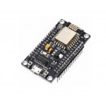
NEW NodeMcu Lua ESP8266 CH340G ESP-12E Wireless WIFI Internet Development Board
Description
ESP8266 is a highly integrated chip designed...Description
ESP8266 is a highly integrated chip designed for the needs of a new connected world. It offers a complete and self-contained Wi-Fi networking solution, allowing it to either host the application or to offload all Wi-Fi networking functions from another application processor.Instruction & Steps of How to use:
1. Download the Arduino IDE, the latest version.
2. Install the IDE
3. Set up your Arduino IDE as: Go to File->Preferences and copy the URL below to get the ESP board manager extensions: http://arduino.esp8266.com/stable/package_esp8266com_index.json Placing the http:// before the URL lets the Arduino IDE use it...otherwise it gives you a protocol error.
4. Go to Tools > Board > Board Manager> Type "esp8266" and download the Community esp8266 and install.
5. Set up your chip as:
Tools -> Board -> NodeMCU 1.0 (ESP-12E Module)
Tools -> Flash Size -> 4M (3M SPIFFS)
Tools -> CPU Frequency -> 80 Mhz
Tools -> Upload Speed -> 921600
Tools-->Port--> (whatever it is)
6. Download and run the 32 bit flasher exe at Github(Search for nodemcu/nodemcu-flasher/tree/master/ at Github)
github.com/nodemcu/nodemcu-flasher/tree/master/Win32/Release
Or download and run the 64 bit flasher exe at:
github.com/nodemcu/nodemcu-flasher/tree/master/Win64/Release
7. In Arduino IDE, look for the old fashioned Blink program. Load, compile and upload.
8. Go to FILE> EXAMPLES> ESP8266> BLINK, it will start blinking.
Chinaندارد۱٬۴۸۳٬۶۰۰ ریال۱ -

NRF24L01+ Radio Transceiver Module 2.4Ghz RF Arduino PI ARM Model Wireless 200M
Description:
Brand new and high quality.
Maximum op...Description:
Brand new and high quality.
Maximum operating speeds up to 2Mbps, GFSK modulation efficiency, Anti-interference ability, Particularly suitable for industrial control applications.
125 Channels, Multi-point communication and frequency hopping to meet the communication needs.
Built-in hardware CRC error detection, Multipoint communication address control.
Low-power 1.9 ~ 3.6V, only 1uA on Power down mode.
Built-in 2.4Ghz antenna.
Available software to set the address, only received local Address when output data(Provide interrupt instruction), can be directly connected to a variety of microcontrollers, Software programming is very convenient.
Built-in voltage regulator.
Standard DIP Pitch Interface for embedded applications.
Size:3.3cm x 1.4cm - 1.29inch x 0.56inch.
Package Includes:
1pc NRF24L01+ Wireless Transceiver Module
Chinaندارد۳۷۵٬۳۰۰ ریال۱ -

NRF51822-02 Data Transmission blue-tooth Module NORDIC BLE4.0 Low Power consumption
NRF51822-02 module is a data transmission module, the BLE Blu
...NRF51822-02 module is a data transmission module, the BLE Bluetooth MCU integrated SOC chip nRF51822-QAFF ,the internal integration of the underlying low power Bluetooth 4.0 standard protocol, module interface is the standard UART interface, built-in interrupt output prompt, When the module receives data from a pair of Bluetooth transmission, it outputs a high level signal, which is used to notify the external device, At the same time, the module is equipped with hardware.make enable foot,In the absence of data transfer,can be set to make the foot high,to disable the function of serial data transmission, thereby reducing the power consumption of the system.
Characteristic:
Low power BLE4.0 Bluetooth single mode chip
The integration of the standard BLE4.0 protocol stack
Standard UART (TTL) interface, can be directly connected to the external MCU serial or serial port
9600 or 38400 optional hardware serial baud rate, the default is 9600
Interrupt output prompt
Hardware enable control
Operating distance: 0~20 m,class II
Power supply voltage: 3.3V
The module comes with a PCB antenna, and can also use the external antenna
Module size: 16.5*28.8mm
Application case:
Short distance automatic data acquisition
Industrial remote control and telemetry
Handheld, handheld machine, POS machine
Wireless keyboard, wireless mouse, game handle
Bluetooth dimming, light control system
Intelligent home control system
Anti drop device
Bluetooth sensor
Mobile phone accessory products
Chinaندارد۱٬۳۴۰٬۶۰۰ ریال۱ -
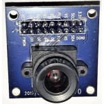

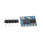
ov7670
Feature: ► Brand new and high quality. ► High sensitivity
...Feature: ► Brand new and high quality. ► High sensitivity for low-light operation. ► Low operating voltage for embedded application. ► Standard SCCB interface compatible with I2C interface. ► Raw RGB, RGB (GRB4:2:2, RGB565/555/444),YUV(4:2:2) and YCbCr(4:2:2)output format. ► Support VGA, CIF and from CIF to 40 x 30 format. ► Vario Pixel method for sub-sampling. ► Auto Image Control: AEC, AGC, AWB, ABF, ABLC. ► Image Quality Control: Color saturation, hue, gamma, sharpness and anti-blooming. ► ISP includes noise reduction and defect correction. ► Support image scaling. ► Lens shading correction. ► Flicker 50/60Hz auto detection. ► Color saturation level auto adjust. ► Edge enhancement level auto adjust. ► De-noise level auto adjust. Parameter: ► Photosensitive Array: 640 x 480. ► IO Voltage: 2.5V to 3.0V. ► Operating Power: 60mW/15fpsVGAYUV. ► Sleeping Mode: <20μA. ► Operating Temperature: -30 to 70 deg C. ► Output Format: YUV/YCbCr4:2:2 RGB565/555/444 GRB4:2:2 Raw RGB Data (8 digit). ► Lens Size: 1/6". ► Vision Angle: 25 degree. ► Max. Frame Rate: 30fps VGA. ► Sensitivity: 1.3V / (Lux-sec). ► Signal to Noise Ratio: 46 dB. ► DynamicRange: 52 dB. ► Browse Mode: By row. ► Electronic Exposure: 1 to 510 row. ► Pixel Coverage: 3.6μm x 3.6μm. ► Duck Current: 12 mV/s at 60℃. ► PCB Size (L x W): Approx. 1.4 x 1.4 inch / 3.5 x 3.5 cm
Chinaندارد۱٬۰۴۵٬۰۰۰ ریال از: ۱٬۰۳۴٬۰۰۰ ریال۱ -

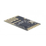
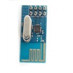
Power enhanced version SMD NRF24L01 Wireless Module NRF24L01+Mini module wireless data transmission module
Description:
Type : Voltage Regulator
Condition : N...Description:
Type : Voltage Regulator
Condition : New
Application : Computer
Supply Voltage : 1
Dissipation Power : 1
Model Number : MW
is_customized : Yes
Wireless Module : SMD NRF24L01
Chinaندارد۴۴۶٬۸۰۰ ریال۱


اطلاعات حساب بانک سامان، شرکت مهندسی بازرگانی توسعه طلیعه نیکان:
شماره حساب 1-2743485-810-875
شماره شبا IR480560087581002743485001
شماره کارت 6219861038201637