ماژول
مقایسه
تصویر
دیتا شیت
نام
توضیح کوتاه
سازنده
اندازه
قیمت
MOQ
سبد خرید
-
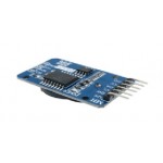


(DS3231 AT24C32 IIC Module Precision Clock Module DS3231SN for Arduino Memory module (with battary
Description
The DS3231 is a low-cost, extremely accurate...Description
The DS3231 is a low-cost, extremely accurate I²C real-time clock (RTC) with an integrated temperature-compensated crystal oscillator (TCXO) and crystal. The device incorporates a battery input, and maintains accurate timekeeping when main power to the device is interrupted. The integration of the crystal resonator enhances the long-term accuracy of the device as well as reduces the piece-part count in a manufacturing line. The DS3231 is available in commercial and industrial temperature ranges, and is offered in a 16-pin, 300-mil SO package.
The RTC maintains seconds, minutes, hours, day, date, month, and year information. The date at the end of the month is automatically adjusted for months with fewer than 31 days, including corrections for leap year. The clock operates in either the 24-hour or 12-hour format with an active-low AM/PM indicator. Two programmable time-of-day alarms and a programmable square-wave output are provided. Address and data are transferred serially through an I²C bidirectional bus.
A precision temperature-compensated voltage reference and comparator circuit monitors the status of VCC to detect power failures, to provide a reset output, and to automatically switch to the backup supply when necessary. Additionally, the active-low RST pin is monitored as a pushbutton input for generating a µP reset.
Features
Accuracy ±2ppm from 0°C to +40°C
Accuracy ±3.5ppm from -40°C to +85°C
Battery Backup Input for Continuous Timekeeping
Operating Temperature Ranges
Commercial: 0°C to +70°C
Industrial: -40°C to +85°C
Low-Power Consumption
Real-Time Clock Counts Seconds, Minutes, Hours, Day, Date, Month, and Year with Leap Year Compensation Valid Up to 2100
Two Time-of-Day Alarms
Programmable Square-Wave Output
Fast (400kHz) I²C Interface
3.3V Operation
Digital Temp Sensor Output: ±3°C Accuracy
Register for Aging Trim
Active-Low RST Output/Pushbutton Reset Debounce Input
Chinaندارد۵۰۰٬۵۰۰ ریال۱ -

1354.17.0001
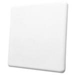
(Antennas WiFi Rail-Trackside, Directional 5 GHz, 23 dBi, Spot-L, IP 67, linear vertical polarized;
... (Antennas WiFi Rail-Trackside, Directional 5 GHz, 23 dBi, Spot-L, IP 67, linear vertical polarized; SISO, Connector N (f
HUBER+SUHNERندارد۱۱۸٬۷۳۹٬۶۰۰ ریال۱ -

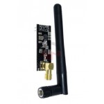
2.4g Nrf24l01 PA LNA SMA Antenna Wireless Transceiver Communication Module
description:
This wireless transceiver module is an easy...description:
This wireless transceiver module is an easy and suitable module if you want to setup your wireless communication system with low cost!! It can achieve a good balance between wireless transition performance and cost! You can easily add it with your own MCU/ARM/PIC/AVR/STM32 system! What\'s more, this NRF24L01+ module is designed with Power amplifier and SMA antenna. This allowed you to use the wireless communication up to 1000 meters! (No barrier)
Frequence: 2.4GHz~2.5GHz
Operating voltage: 3 ~ 3.6V Max
Current: 115mA
Multi-frequency: 125 frequency
Support up to six channels of data reception
Communication distance: up to 1000 meters (No barrier)
Chinaندارد۹۱۱٬۶۰۰ ریال۱ -

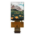
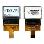
AFY240320A0-2.8
Doc.No: AFY240320A0-2.8N6NTN-R REVA0 PAGE1/21 EFFECTIVE DATE2013-03-26 SPECIFICATION OF LCD MODU.
ORIENT DISPLAYندارد۶٬۸۵۴٬۳۰۰ ریال۱ -

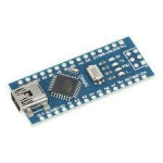
Arduino compatible development board with Nano-based microcontroller USB serial converter ATmega328P and CH340
Description:
Arduino NANO with ATmega32...Description:
Arduino NANO with ATmega328 Microcontroller is an ultra-low size Arduino board with AVR architecture and based on Atmel Atmega328P-AU microcontroller, which includes all capabilities of Arduino Duemilanove except DC power jack in the smallest size.
This miniature board is like an Arduino UNO type, but with a smaller size, which is suitable for a flyer and tiny robot. This Arduino is idealized for breadboard working too.
The Arduino NANO is equipped with 8 pins for analog inputs (to run 10-bit resolution means 1024 different values), and 14 digital IO pins that 6 pins can be used for PWM outputs, 2pins for serial receive and transmit data, 2pins for external interrupts, 4pins for SPI serial ports, and on for LED indicator. It also has a pin for reference voltage input for analog reference comparison and one pin for reset the microcontroller.
This Arduino chip operates with a TTL logic level of 3.3V DC and can be supplied with a recommended voltage of 7V to 9V DC. It can easily be supplied through a micro-USB to USB cable from any USB port or through the AC to DC or a 9V battery. It is also compatible with 1.0 Arduino pinout and any shields with 3.3V DC.
Arduino NANO can withstand maximum input and output voltage of 3.3V, which means that applying more than 3.3V DC to any input or output pins may damage the board. This board has all the requirements of the microcontroller support.
Arduino is an open-source platform based on simple userfriendly hardware and software.
The Arduino board can be employed as a slave operator, that performs simple digit works based on instructions.Features:
Microcontroller: ATmega328
Architecture: AVR
Operating Voltage: 5 V
Flash Memory: 32 KB of which 2 KB used by bootloader
SRAM: 2 KB
Clock Speed: 16 MHz
Analog IN Pins: 8
EEPROM: 1 KB
DC Current per I/O Pins: 40 mA (I/O Pins)
Input Voltage: 7~9 V MAX
Digital I/O Pins: 22 (6 of which are PWM)
PWM Output: 6
Power Consumption: 19 mA
PCB Size: 18mm x 45 mm
ARDUINOندارد۹۳۵٬۰۰۰ ریال از: ۹۰۷٬۵۰۰ ریال۱ -
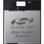

BGM13P32F512GE-V2
Bluetooth Modules (802.15.1) BGM13P32F512GE Bluetooth module Supports high-throughput, long range, a
... Bluetooth Modules (802.15.1) BGM13P32F512GE Bluetooth module Supports high-throughput, long range, and regular Bluetooth LE PHYs
Silicon Labsندارد۶٬۰۹۹٬۱۰۰ ریال۱ -
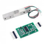

DIYmall 2pcs Hx711 Weight Weighing Load Cell Conversion Module Sensors Ad Module for Arduino Microcontroller
Product description
Package contents:
1 x Load cell...Product description
Package contents:
1 x Load cell 0-5KG
1 x HX711 24BIT Precision ADC Module on breakout board
10 x Breakaway header pins for HX711 connection
Everything you need to take accurate force measurements with and Arduino, Raspberry Pi, or other microcontroller in one complete package!Information:
Load cell - Sturdy aluminum alloy construction. Strain gauges pre-attached with strain relieved wires. Accurately measures forces from 0-5kg (0-11 lb).
HX711 - This top of the line load cell amplifier mounted on a breakout board pairs perfectly with the load cell to provide fast, accurate force measurements. It measures small changes in the resistance of the strain gauges mounted to the load cell and passes these values directly to any microcontroller (like an Arduino or Raspberry Pi).
Load cell specs:
-Wire leads pre-attached, 22 cm (8.5 in) long
-Dimensions 12.7 mm high, 12.7 mm wide, 80 mm long (0.5 in x 0.5 in x 3.15 in)
-4 mounting holes, 15 mm spacing on each side. One side both holes tapped M4 thread, the other side both holes tapped M5 thread.HX711 specs:
-Operation Voltage: 2.7V–5V
-Operation Current: < 1.5mA
-Mounted on breakout board
-Includes breakaway headers for connection, soldering requiredConnections:
Red to E+
Black to E-
Green to A+
White to A-
Degrawندارد۸۴۰٬۱۰۰ ریال۱ -

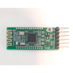
DSD TECH SH-HC-08 Bluetooth 4.0 BLE Slave Module to UART Transceiver for Arduino Compatible With IOS
Technical Data:
TXD: serial transmit, 3.3V TTL level....Technical Data:
TXD: serial transmit, 3.3V TTL level.
RXD: serial receiver, 3.3V TTL level.
CTS: serial flow control, is not supported.
RTS: serial flow control, is not supported.
DC: simulation, burning clock pin.
DD: simulation, data burning feet.
RST: reset pin module requires low level of not less than 5ms reset.
VCC: module power foot, requiring DC 3.3V power supply current is not less than 100mA.
GND: module common ground.
LED: LEDs module output pin, high output, series resistor connected LED.
Slave bright one second every two seconds. Once connected, LED lit.
KEY:. Input pin, internal pulldown This foot high, clear the record for the host address from the machine.
PIO: extended functionality for setting the module master-slave mode, the default internal pull-up resistor from the machine; external 1K pull-down resistor connected to ground, as the host. Currently only supports 9600bps communication, does not support the AT commands. Host, when pass-through traffic from the machine, there must be a certain time interval between packets. For example, the packet length is 500 bytes, then the transmission time interval between packets can be set to no less than 600ms. Otherwise, you may lose data.
Abraconندارد۳٬۰۵۲٬۵۰۰ ریال۱ -
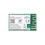

E73-2G4M04S1D
Ebyte nRF51822 BLE 4.2 Low power E73-2G4M04S1D 2.4GHZ 4dBm RF Bluetooth Module
EBYTESMD۱٬۵۱۹٬۳۰۰ ریال۱ -

ESP-12E
ESP8266 ESP-12F Serial WIFI Model ESP-12E Upgrade Remote Wireless WIFI Module ESP12F ESP12
Chinaندارد۷۷۰٬۰۰۰ ریال از: ۷۵۶٬۳۰۰ ریال۱ -
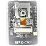

esp32-cam
Features: - Ultra-small 802.11b/g/n Wi-Fi + BT/BLE SoC module
...Features: - Ultra-small 802.11b/g/n Wi-Fi + BT/BLE SoC module - Low-power dual-core 32-bit CPU for application processors - Up to 240MHz, up to 600 DMIPS - Built-in 520 KB SRAM, external 4M PSRAM - Supports interfaces such as UART/SPI/I2C/PWM/ADC/DAC - Support OV2640 and OV7670 cameras with built-in flash - Support for WiFI upload -Support TF card - Support multiple sleep modes - Embedded Lwip and FreeRTOS - Support STA/AP/STA+AP working mode - Support Smart Config/AirKiss One-click distribution network - Support for serial local upgrade and remote firmware upgrade (FOTA) Description: CES NEWS' Geekcreit ESP32-CAM WiFi + Bluetooth Camera Module Development Board ESP32 With Camera Module OV2640 2MP - Board & Shield Motherboard & Development Board. The ESP32-CAM has a very competitive small-size camera module that can operate independently as a minimum system, measuring the only 27*40.5*4.5mm, with deep sleep current and a minimum of 6mA. ESP-32CAM can be widely used in various IoT applications. It is suitable for home smart devices, industrial wireless control, wireless monitoring, QR wireless identification, wireless positioning system signals and other IoT applications. It is an solution for IoT applications. ESP-32CAM is packaged in and can be directly plugged into the backplane for quick production. It provides customers with a highly reliable connection method and is convenient for use in various IoT hardware terminals. Note: This product contains the OV2640 Camera Module. If you need to use the OV7670 camera, please purchase it separately. Package Included: 1 x ESP32-CAM Module 1 x Camera Module OV2640 2MP Product Specifications: ESP32-CAM Picture Output Format Rate: Test environment: camera model: OV2640 XCLK: 20
Chinaندارد۲٬۵۰۲٬۵۰۰ ریال۱ -
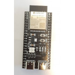

ESP32-S3-WROOM-1
About this item 32 bit MCU, 2.4 GHz WiFi + Bluetooth LE SoC Suppor
...About this item 32 bit MCU, 2.4 GHz WiFi + Bluetooth LE SoC Supporting IEEE 802.11 b/g/n and Bluetooth 5 Based on ESP32-S3-WROOM-1 8MB Flash + 2 MB PSRAM About ESP32-S3 hardware resources ESP32-S3 is a low-power MCU-based SoC that supports 2.4 GHz Wi-Fi and Bluetooth Low Energy (Bluetooth LE). ESP32-S3 has a complete Wi-Fi subsystem and a Bluetooth LE subsystem, State-of-the-art power and RF performance. S3 provides a rich set of peripheral interfaces, and supports ultra-low-powerapplications. Different security features allow the device to meet stringent security requirements. Instructions for using the USB cable The on-board USB port of the YD-ESP32-S3 core board is the Type-C interface.It can communicate with the computer and provide power. The cable can be used: USB Type A to Type-C cable or CC cable Note the distinction between the commonly used USB A port to Type-C cable that can only be charged, which cannot be used for communication between YD-ESP32-S3 and the host.
Chinaندارد۲٬۵۱۹٬۰۰۰ ریال از: ۲٬۴۷۵٬۰۰۰ ریال۱ -

ESP32-WROOM-32
WiFi Modules (802.11) Module 4 MB Flash ESP32-D0WDQ6
Espressif Systemsندارد۱٬۸۸۳٬۸۰۰ ریال از: ۱٬۸۵۶٬۳۰۰ ریال۱ -

ESP32-WROOM-32D
WiFi Modules (802.11) SMD Module, ESP32-D0WD, 32Mbits SPI flash, UART mode, PCB antenna
Espressif Systemsندارد۱٬۵۹۰٬۸۰۰ ریال از: ۱٬۵۵۵٬۱۰۰ ریال۱ -

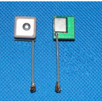
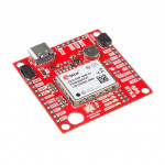
GBA-922 Ver1.0
Selling unit: Single article Individual package size: 3X4X5 cm Weight per unit:0.5 kg Type of pac
... Selling unit: Single article Individual package size: 3X4X5 cm Weight per unit:0.5 kg Type of packaging: standard package Ceramic GPS active reception antenna 12 * 12mm 12 L * 12 W * 6mm thick Gain 27DB, the equivalent of two to enlargeStability life, easy to damage. GPS active ceramic receiving antenna
Italyندارد۱٬۷۶۹٬۶۰۰ ریال۱ -

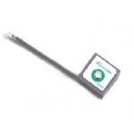
GBA-936
The active embedded patch antenna with circularly polarized... The active embedded patch antenna with circularly polarizedradiation pattern features directional operation to be used ina navigation scenario, where the antenna alwayskeep facing sky to receive satellite signals effectively.For different request of cable and connector, please contact us or our local distributors to have a customized solution.
Abraconندارد۲٬۷۳۴٬۸۰۰ ریال۱


اطلاعات حساب بانک سامان، شرکت مهندسی بازرگانی توسعه طلیعه نیکان:
شماره حساب 1-2743485-810-875
شماره شبا IR480560087581002743485001
شماره کارت 6219861038201637